

Compressed Air & Gas Dryers
Biogas & Natural Gas Dryer
Dry, steady fuel gas for your engines and boilers, with no liquid water in the line and no methane vented.
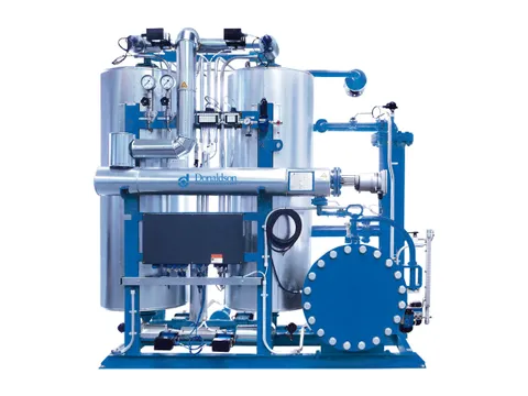
Product overview
Dry fuel gas, from the digester to your engine
Biogas leaves the digester fully saturated, and every metre of pipe cooler than the digester condenses part of its water. At 38 °C, water vapour makes up about 6.4 % of the gas by volume, or 46 g in every actual cubic metre.
Our dryer chills the gas with a water-glycol circuit, usually to 3–10 °C, so the excess water condenses, separates and drains through liquid-seal traps without letting gas escape. It then reheats the gas: chilled to 5 °C and reheated to 25 °C, it leaves at a relative humidity of about 28 %.
It handles digester biogas, landfill and sewage gas, biomethane and natural gas, and is built for hazardous areas, close to the digester, gas storage or engine it serves. With an adsorption stage, it also dries pressurised gas to pressure dew points below 0 °C, with no methane vented.
- 88 %Of the incoming water removed, 38 °C in and 5 °C out
- 3–10 °CTypical chilling set point, which sets the dew point
- About 28 %Relative humidity after reheating to 25 °C
- ZeroMethane vented
Benefits
The problems it solves
Warm, saturated gas condenses water wherever it cools. Here is what that water does to your gas plant, and how the dryer stops it.
-
Engines tripping on low gas pressure
The problem
A water column only 10 mm high balances 1 mbar of gas pressure, so a small pool of condensate at a low point restricts or stops the flow.
How it solves it
With a dew point below every downstream temperature, no condensate pools in your gas lines, and engine trips caused by water end.
-
Acid attack on engines and pipes
The problem
H₂S and CO₂ dissolve in condensate and form an acid that corrodes pipework, blowers and valve seats, and attacks engine bearings and cylinder liners.
How it solves it
Dry gas reduces acid formation, oil degradation and deposits, extending your oil change intervals and time between overhauls.
-
Short carbon filter life
The problem
Water vapour competes with siloxanes for adsorption sites, and wet gas lets siloxanes break through to burn to abrasive silica in the engine.
How it solves it
Reheated gas at low relative humidity keeps adsorption sites free for siloxanes and H₂S, so your activated carbon lasts longer.
-
Unsteady engine output
The problem
Varying water content alters the heating value of the gas, disturbing air-fuel ratio control and raising the risk of misfiring and knocking.
How it solves it
Constant water content gives a constant heating value, so your engines hold their rated electrical output with fewer control corrections.
-
Gas escaping at drains
The problem
Uncontrolled condensate drainage releases methane and H₂S, and H₂S deadens the sense of smell above about 100 ppm.
How it solves it
Water leaves the gas at one defined point, through liquid-seal traps that drain it without letting gas escape.
-
Ice and hydrates in CNG
The problem
At CNG storage pressures of 200–250 bar, water condenses far above its atmospheric dew point, and ice and hydrates block regulators, filters and dispenser valves.
How it solves it
With an adsorption stage, pressurised gas is dried to pressure dew points below 0 °C, with its regeneration gas kept inside the process.
Where it’s used
Wherever gas is burned, upgraded or compressed
From farm digesters to fuelling stations, anywhere wet fuel gas has to reach an engine, burner or compressor dry.
-
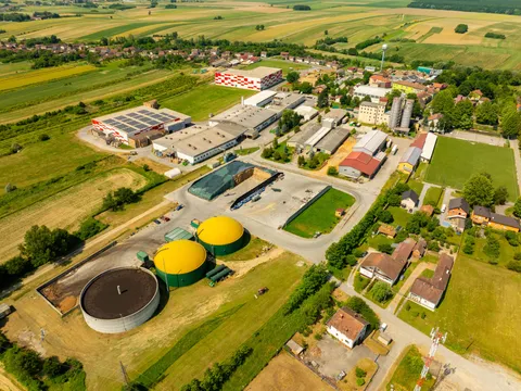
Agricultural biogas plants
Gas from manure, energy crops and residues, dried before the combined heat and power engines.
-
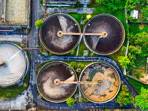
Municipal wastewater
Sewage gas for on-site engines and boilers, dried ahead of activated carbon to keep siloxane deposits out of the engines.
-
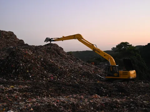
Landfill sites
Saturated gas collected under vacuum, dried to protect blowers, flares and gas engines.
-
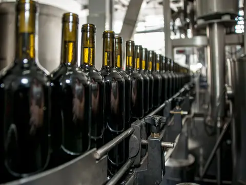
Food and beverage processing
Breweries, dairies, sugar mills, distilleries and starch plants burning biogas from their wastewater and residues in boilers.
-
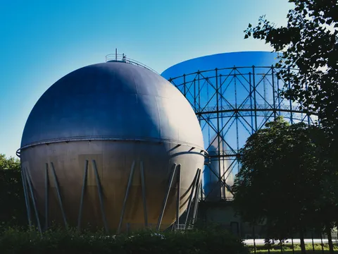
Biomethane upgrading
Dried raw biogas for membrane, pressure swing adsorption, amine and water scrubbing plants.
-
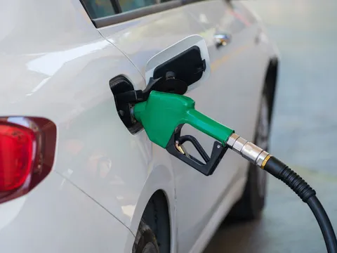
CNG and bio-CNG stations
Gas dried so that no water, ice or hydrates form at vehicle storage pressure.
Also pulp and paper effluent plants, natural gas distribution and industrial users, oil and gas production, and laboratories and pilot plants.
How it works
Precool, chill, separate, reheat
A chilled water-glycol circuit cools your gas until its water condenses out. The dry gas is then warmed back up, well below saturation, before it moves on.
-
1. PrecoolWarm, saturated raw gas enters the gas-to-gas heat exchanger and gives up heat to the cold dried gas. Water begins to condense and drains to a liquid-seal trap.
-
2. ChillThe gas flows through the chilled heat exchanger, against the flow of the water-glycol coolant, and cools to its set point, typically 3–10 °C. Most of the water condenses.
-
3. Separate and drainThe separator and its demister catch the condensed droplets, and liquid-seal traps drain the condensate without letting gas escape. Ammonia, part of the H₂S and CO₂, and part of the siloxanes leave with it.
-
4. Reheat and boostThe dried gas returns through the gas-to-gas heat exchanger and warms by 15–20 K: chilled to 5 °C and reheated to 20 °C, its relative humidity falls to about 37 %. The blower then raises it to supply pressure, commonly 50–200 mbar, and adds compression heat.
-
5. The chilled glycol circuitA pump circulates the water-glycol coolant through the heat exchanger and back to the chiller, which rejects the heat to ambient air or cooling water. Glycol keeps the coolant from freezing, and its temperature is held high enough that no ice forms on the gas side.
Example figures for raw biogas saturated at 38 °C, near atmospheric pressure, chilled to 5 °C.
Get the full details
Our brochure covers it in detail, and our questionnaire tells us what we need to recommend the right one for your plant.
Keep exploring
More from our range
Equipment for every stage of your compressed air, and our own engineers to test, commission and look after it.
-
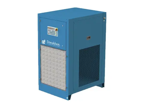
Refrigerated Air Dryers
Dry, condensate-free air for your plant, with no compressed air spent drying.
View product -
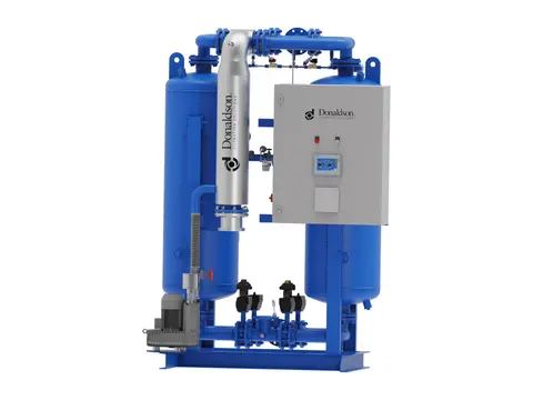
Heated Desiccant Dryers
Deep, stable dew points for your air, with heat doing the regeneration.
View product -
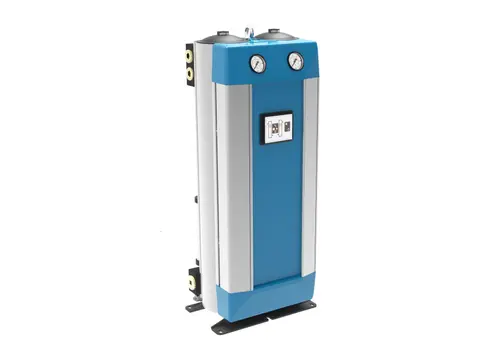
Heatless Desiccant Dryers
Deep dew points without heaters, for hazardous areas and remote sites.
View product -
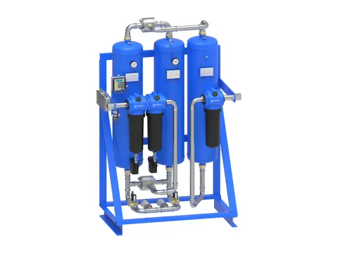
Breathing Air Systems
Your plant’s compressed air, made safe to breathe.
View product -
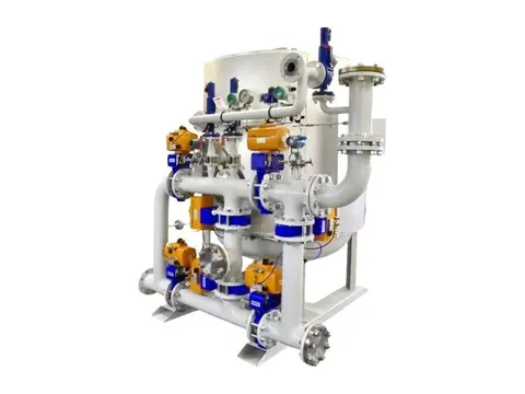
Hydrogen Dryers & De-Oxo Units
Electrolytic hydrogen purified of oxygen and water, ready for fuel cells.
View product -
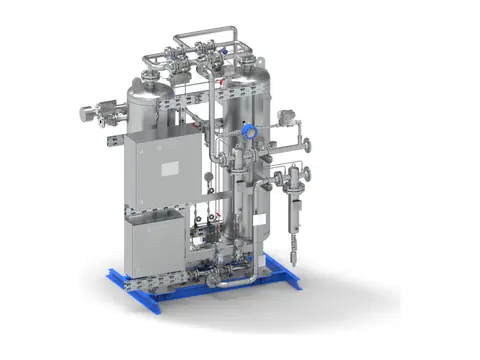
CO₂ Dryers
Beverage-grade dry CO₂ for your recovery plant, with no gas vented.
View product -
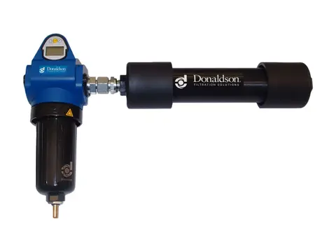
Membrane Dryers
Dry air at the point of use, with no power and no moving parts.
View product
-
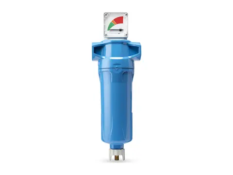
Coalescing Filters
Takes oil and water aerosols out of your air, down to 0.01 mg/m³.
View product -
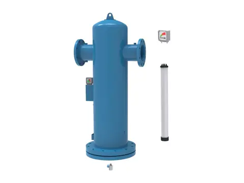
Particulate Filters
Dry, dust-free air for your plant, down to 0.01 µm particles.
View product -
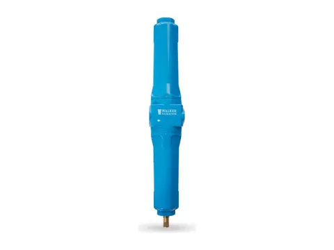
Compressed Air Duplex Filters
Change filter elements without interrupting your air supply.
View product -
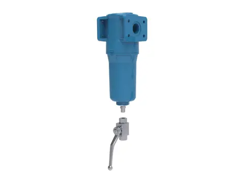
High Pressure Filters
Certified air purity for your high-pressure lines, up to 350 bar g.
View product -
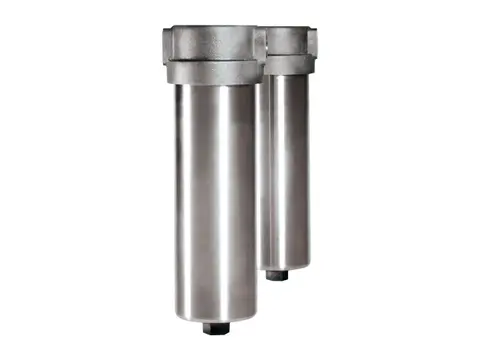
High Temperature Filters
Particle-free compressed air and gas where your process runs hot.
View product -
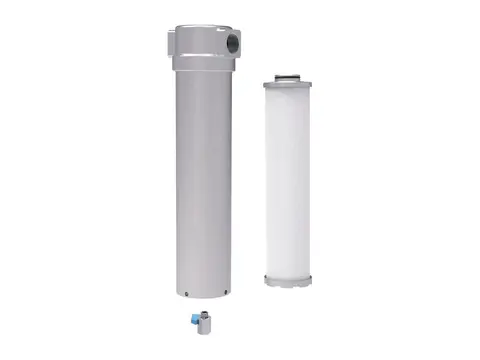
Ammonia and Refrigerant Filters
Keeps compressor oil out of your condensers and evaporators.
View product -
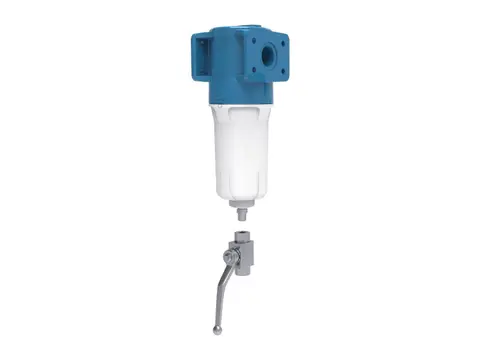
Oxygen Filters
Particle-free oxygen for your system, without adding an ignition source.
View product -
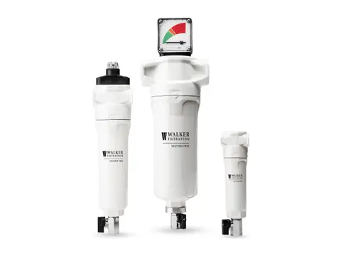
Silicone-Free Filters
Crater-free paint finishes, from air free of paint-wetting contaminants.
View product -
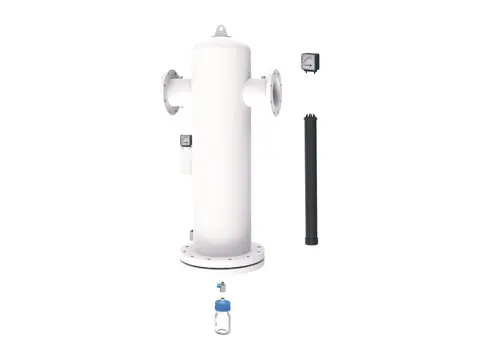
Medical Vacuum Filters
Keeps pathogens from hospital suction away from your pumps and exhaust.
View product -
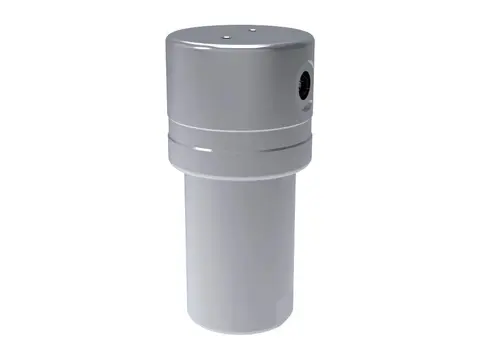
Hydrogen Filters
Particle, aerosol and oil-free hydrogen, from electrolyser to dispenser.
View product -
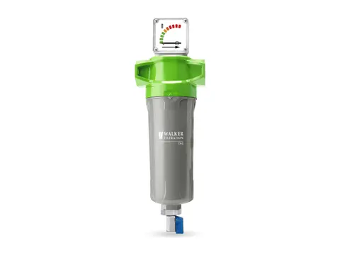
CNG Filters
Oil-free, particle-free natural gas from your compressor to the vehicle.
View product
-
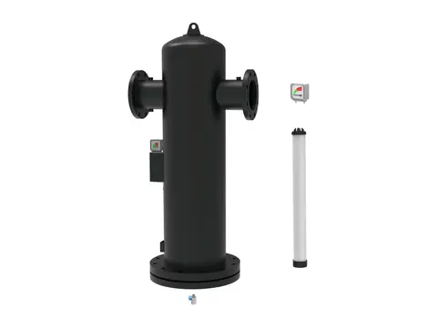
Centrifugal Moisture Separators
Bulk liquid out of your air by centrifugal force, with no element to replace.
View product -
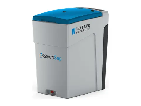
Oil Water Separator
Turns oily compressor condensate into water fit for sewer discharge.
View product -
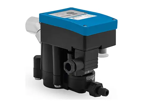
Zero-Loss Electronic Drain
Discharges every drop of condensate from your system, never your compressed air.
View product -
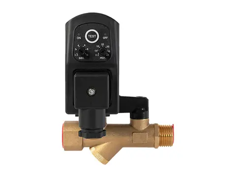
Timer Drain
Scheduled, positive condensate discharge from any collection point in your system.
View product -
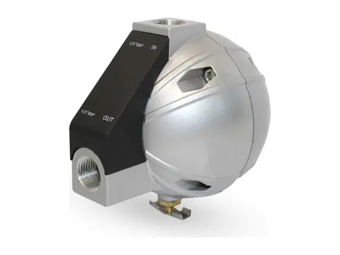
Mechanical Float Drain
Buoyancy-driven condensate removal with no power and no air loss.
View product -
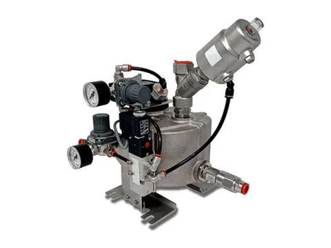
Vacuum Drain
Empties liquid from your vacuum system without breaking the vacuum.
View product
-
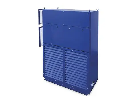
Crane Air Conditioner
Cool, clean cabins and electrical rooms for cranes working in extreme heat.
View product -
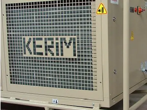
Tent Air Conditioner
Controlled climate for your tents, shelters and temporary structures.
View product -
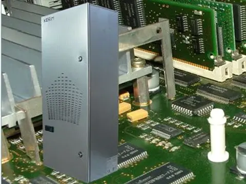
Panel Air Conditioner
Cool, clean, dry control panels, even in your hottest, dirtiest plant areas.
View product -
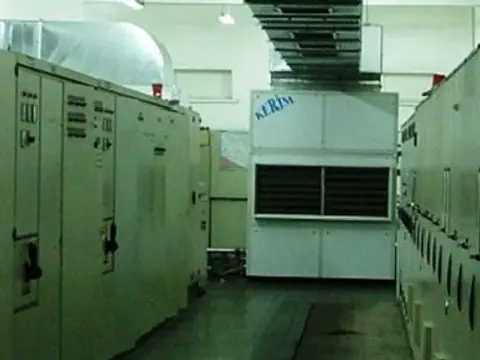
Air / Water Cooled Air Conditioner
Stable room temperatures for your electrical rooms in extreme plant heat.
View product
-
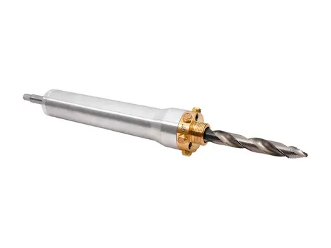
Hot Tapping
Add measurement ports to your live air lines without stopping production.
View product -
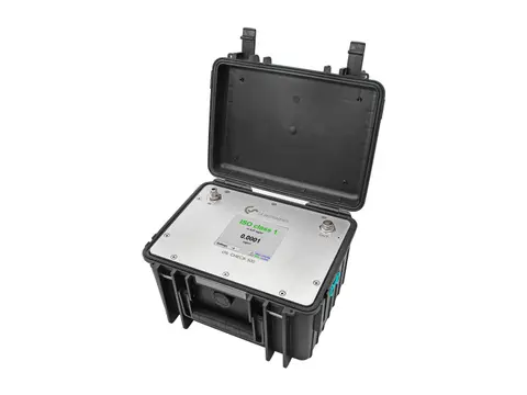
Compressed Air Quality Measurement
Prove your air's ISO 8573-1 purity: particles, oil and dew point.
View product -
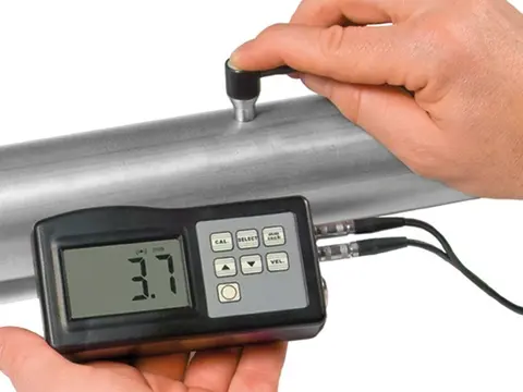
Digital Thickness Meter
Measure the metal left in your receivers and pipework, from the outside.
View product -
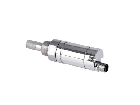
Dew Point Meter
Proof your air is dry, measured at line pressure.
View product -
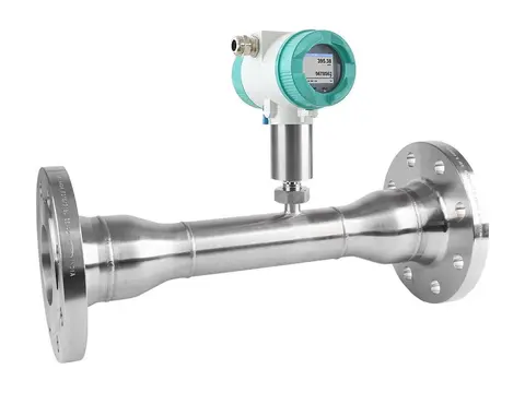
Flow Meter
True standard flow of your compressed air, whatever the line pressure.
View product -

Leak Detector
Hear, locate and cost every compressed air leak in your plant.
View product -
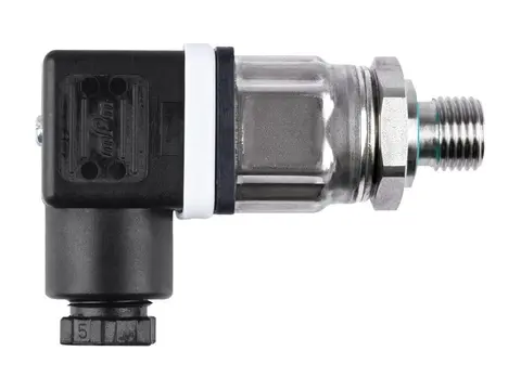
Pressure Sensor
Live pressure data from your compressor room to every point of use.
View product -
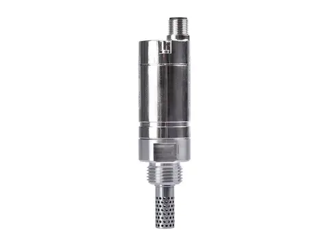
Humidity Meter
Humidity, temperature and dew point from one probe.
View product -
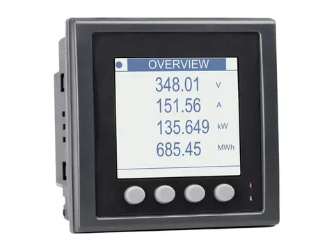
Power Meter
Measure the true power, energy and efficiency of your compressors.
View product
-
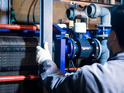
Health Testing of Compressed Air & Gas Dryers
Measured proof your dryer delivers its rated dew point.
View service -
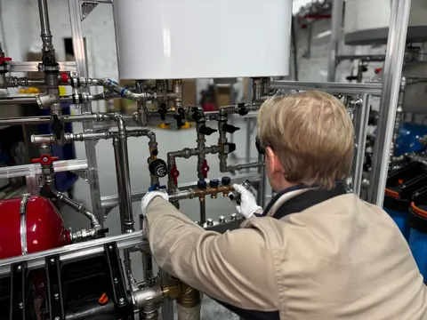
Commissioning and Service of Compressed Air & Gas Dryers
Verified dew point from first start-up through your dryer's service life.
View service -
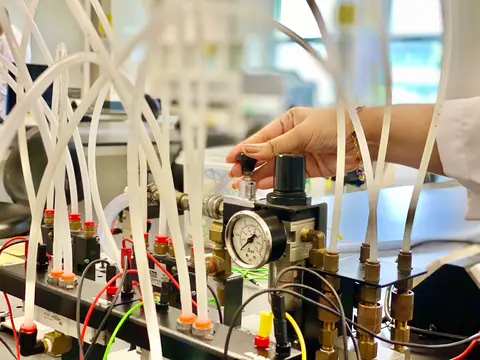
Compressed Air Quality Testing
Measured, documented proof of your compressed air purity class.
View service -
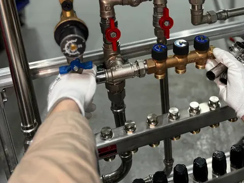
Dew Point Measurement Testing
Verified pressure dew point at the points that matter in your network.
View service -
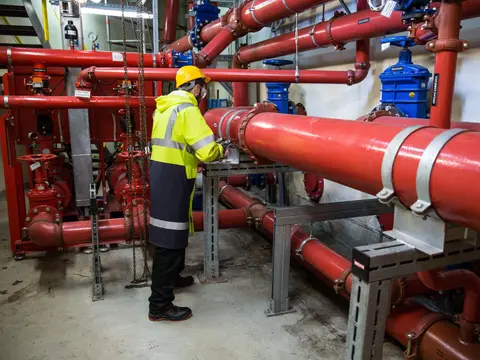
Compressed Air Flow Testing
Measured air demand, leakage and cost for your plant, not estimates.
View service -
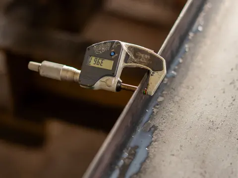
Wall Thickness Testing
Know the remaining wall, corrosion rate and safe life of your equipment.
View service -
Sourcing
Spares, consumables and whole systems for your plant, sourced globally.
View service
