
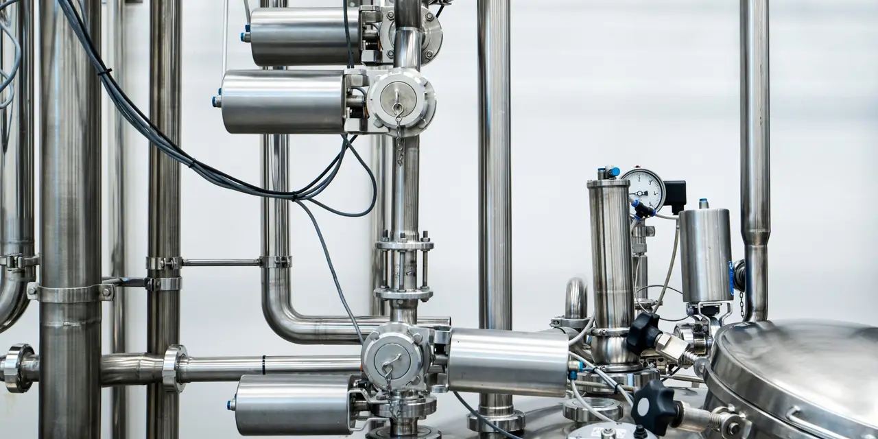
Compressed Air & Gas Filters
Ammonia and Refrigerant Filter
Keep compressor oil where it belongs, in the compressor, and out of the condensers and evaporators your cooling depends on.
Product overview
Oil-free refrigerant, cleaner coils, steadier cooling
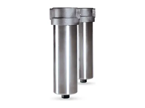
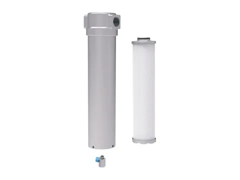
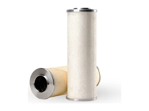
Every lubricated refrigeration compressor releases oil into the gas it compresses. Your primary oil separator takes out the bulk liquid, but the gas leaving it still carries a fine mist of droplets, mostly below a few micrometres, that gravity cannot settle. Our coalescing filter captures that mist in a fibre bed, merges it into draining liquid, and sends the oil back to the compressor or into an oil collection pot.
Oil that escapes settles where the refrigerant is coldest and moves slowest: in evaporators, low-pressure receivers, surge drums and suction accumulators. There it insulates heat transfer surfaces, and in ammonia plants it has to be drained by hand, exposing operators to ammonia.
The filters work in ammonia (R717), carbon dioxide (R744), hydrocarbons, and HFC and HFO refrigerants. Particulate elements in the same family protect compressor suction, oil return lines and the small orifices of expansion and float valves.
- About 42 %Heat transfer lost to a 0.1 mm oil film, in an evaporator example
- About 2.6 %Ideal-cycle efficiency lost per kelvin lower evaporating temperature
- About 3.4 %Capacity lost per 0.1 bar suction pressure drop, ammonia at −10 °C
- R717 and R744Ammonia and carbon dioxide, plus hydrocarbons, HFCs and HFOs
Benefits
The problems it solves
Oil carryover is inherent to lubricated compression. Here is what that oil does once it leaves the compressor, and how the filter stops it.
-
Fouled evaporators
The problem
Oil thickens at low temperature and coats evaporator tubes, forcing the plant to run a lower evaporating temperature for the same duty.
How it solves it
Clean heat transfer surfaces keep the evaporating temperature at its design value, avoiding the ideal-cycle loss of about 2.6 % per kelvin.
-
Rising head pressure
The problem
An oil film on condenser tubes or plates adds heat transfer resistance and raises condensing pressure.
How it solves it
Oil-free condenser surfaces keep your head pressure down, reducing compressor power and discharge temperature.
-
Hazardous oil draining
The problem
Oil drained from ammonia low-pressure vessels releases dissolved ammonia as it warms, exposing operators at every drain.
How it solves it
Less oil reaches the low-pressure side, so your operators spend less time at oil drain points.
-
A compressor short of oil
The problem
Oil that leaves the package lowers the charge, starving bearings and the rotor seal, and a low level trips the compressor.
How it solves it
Recovered oil returns to the compressor, keeping its charge stable and reducing how often and how much oil you add.
-
Debris in rotors and valves
The problem
Weld slag, grinding dust and mill scale can score a rotor, hold a valve off its seat or stop a float mechanism.
How it solves it
Suction and liquid line particulate elements keep debris away from rotors, bearings and valves, especially during commissioning.
-
Faults found too late
The problem
A failing separator or oil level fault is usually found only when the evaporators foul.
How it solves it
The drain sight glass and differential pressure reading show a rise in oil carryover before oil reaches the evaporators.
Where it’s used
Wherever refrigeration keeps the process running
From frozen warehouses to fertiliser terminals, industrial refrigeration relies on clean evaporators and a compressor that keeps its oil.
-

Food, cold storage and beverages
Frozen warehouses at −25 to −30 °C, meat, poultry and seafood freezing, dairy, ice cream, and brewery fermentation cooling.
-

Chemicals, petrochemicals and fertilisers
Reactor jacket cooling, crystallisation, propane and propylene refrigeration, and boil-off gas reliquefaction at ammonia storage terminals.
-

Fishing vessels and marine refrigeration
Refrigerated seawater systems, onboard freezers and cargo holds.
Also pharmaceutical process cooling, CO₂ recovery plants, supermarket CO₂ transcritical and cascade systems, ice rinks, industrial heat pumps and district heating, HVAC chillers and data centre cooling, and test chambers.
How it works
Catch the mist, return the oil
The filter sits directly after the primary oil separator, in the hot gas line and before the condenser, so one filter protects every component downstream.
-
1. Hot gas and oil mistThe screw compressor discharges hot gas carrying oil. The primary oil separator removes the bulk liquid, but a fine mist of droplets follows the gas out.
-
2. Capture in the fibresThe gas turns down into the element core and passes from inside to outside through a deep bed of fine fibres. Droplets are caught by impaction above about 1 µm, interception from about 0.3 to 1 µm, and diffusion below about 0.1 µm.
-
3. Coalesce and drainCaptured oil joins the oil already on the fibres, is pushed to the outer face, and runs down the drainage layer into the sump in drops of millimetre size.
-
4. Oil back to the compressorThe sump drains continuously through a sight glass and metering orifice back to the compressor oil system, or to an oil pot. The sight glass shows the oil is returning.
-
5. Oil-free gas onThe oil-free gas goes on to the condenser, receiver and evaporators. The differential pressure gauge shows the element’s condition.
Get the full details
Our brochure covers it in detail, and our questionnaire tells us what we need to recommend the right one for your plant.
Keep exploring
More from our range
Equipment for every stage of your compressed air, and our own engineers to test, commission and look after it.
-
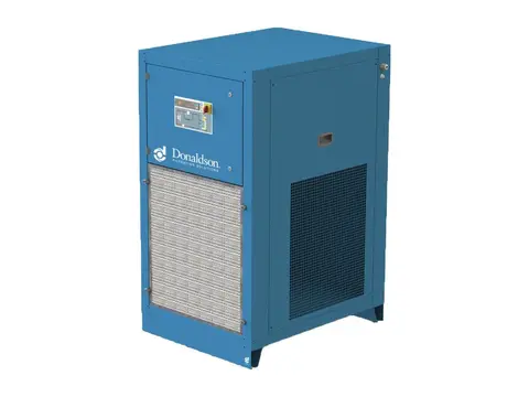
Refrigerated Air Dryers
Dry, condensate-free air for your plant, with no compressed air spent drying.
View product -
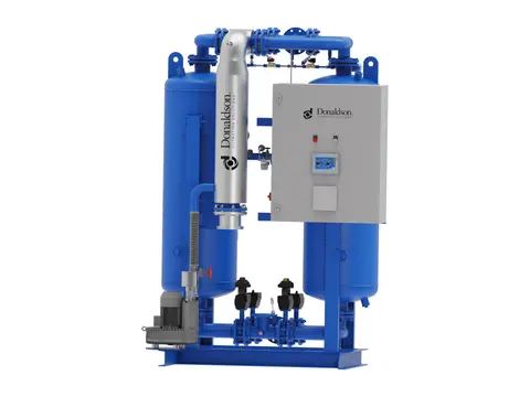
Heated Desiccant Dryers
Deep, stable dew points for your air, with heat doing the regeneration.
View product -
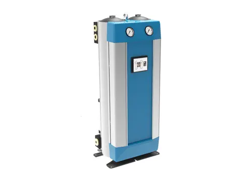
Heatless Desiccant Dryers
Deep dew points without heaters, for hazardous areas and remote sites.
View product -
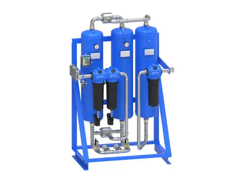
Breathing Air Systems
Your plant’s compressed air, made safe to breathe.
View product -
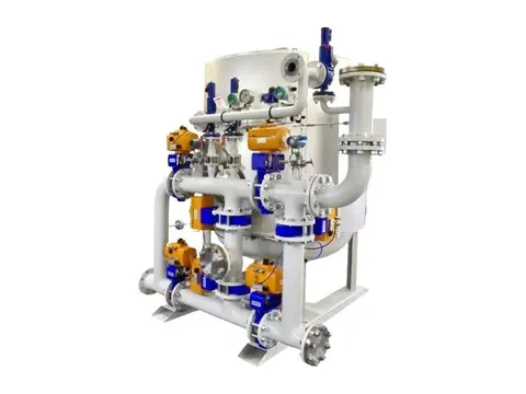
Hydrogen Dryers & De-Oxo Units
Electrolytic hydrogen purified of oxygen and water, ready for fuel cells.
View product -
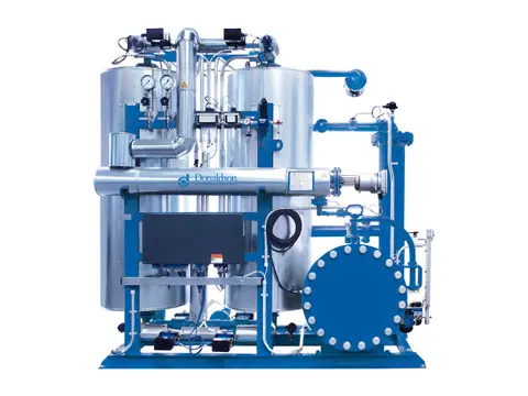
Biogas & Natural Gas Dryers
Dry, condensate-free fuel gas for your engines, boilers and upgrading plant.
View product -
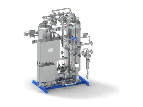
CO₂ Dryers
Beverage-grade dry CO₂ for your recovery plant, with no gas vented.
View product -
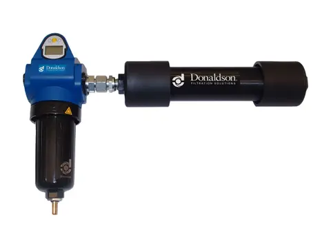
Membrane Dryers
Dry air at the point of use, with no power and no moving parts.
View product
-
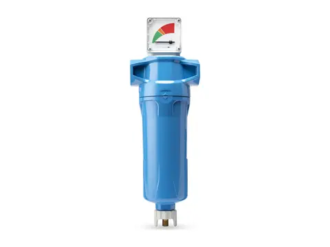
Coalescing Filters
Takes oil and water aerosols out of your air, down to 0.01 mg/m³.
View product -
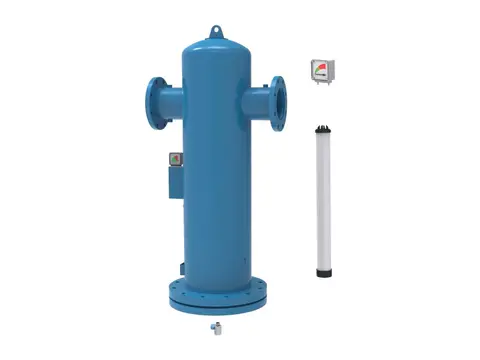
Particulate Filters
Dry, dust-free air for your plant, down to 0.01 µm particles.
View product -
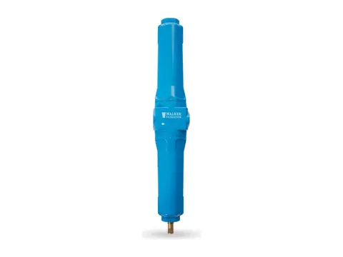
Compressed Air Duplex Filters
Change filter elements without interrupting your air supply.
View product -
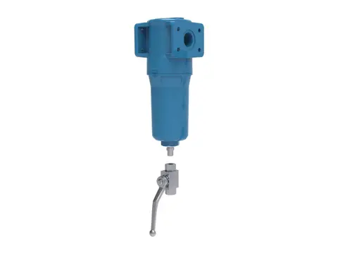
High Pressure Filters
Certified air purity for your high-pressure lines, up to 350 bar g.
View product -
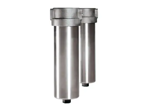
High Temperature Filters
Particle-free compressed air and gas where your process runs hot.
View product -
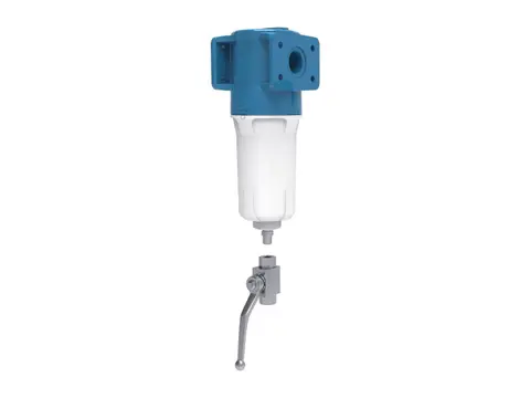
Oxygen Filters
Particle-free oxygen for your system, without adding an ignition source.
View product -
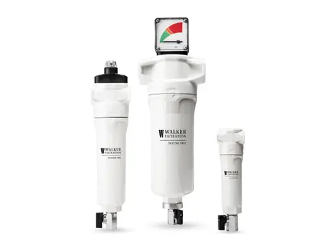
Silicone-Free Filters
Crater-free paint finishes, from air free of paint-wetting contaminants.
View product -
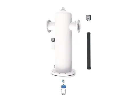
Medical Vacuum Filters
Keeps pathogens from hospital suction away from your pumps and exhaust.
View product -
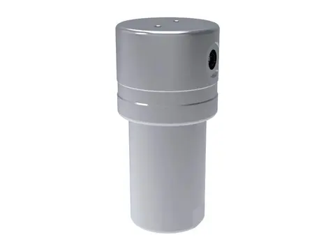
Hydrogen Filters
Particle, aerosol and oil-free hydrogen, from electrolyser to dispenser.
View product -
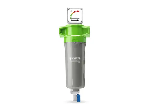
CNG Filters
Oil-free, particle-free natural gas from your compressor to the vehicle.
View product
-
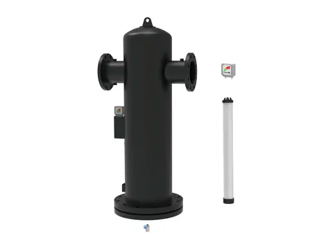
Centrifugal Moisture Separators
Bulk liquid out of your air by centrifugal force, with no element to replace.
View product -
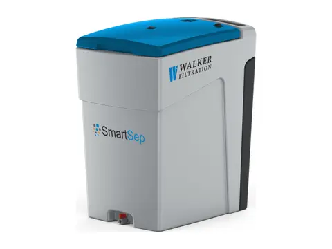
Oil Water Separator
Turns oily compressor condensate into water fit for sewer discharge.
View product -
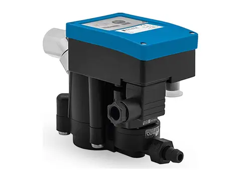
Zero-Loss Electronic Drain
Discharges every drop of condensate from your system, never your compressed air.
View product -
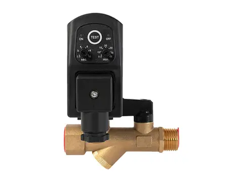
Timer Drain
Scheduled, positive condensate discharge from any collection point in your system.
View product -
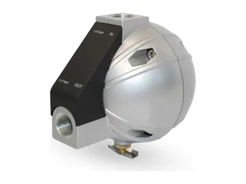
Mechanical Float Drain
Buoyancy-driven condensate removal with no power and no air loss.
View product -
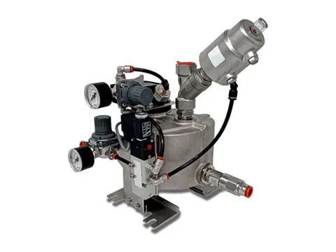
Vacuum Drain
Empties liquid from your vacuum system without breaking the vacuum.
View product
-
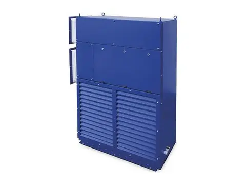
Crane Air Conditioner
Cool, clean cabins and electrical rooms for cranes working in extreme heat.
View product -
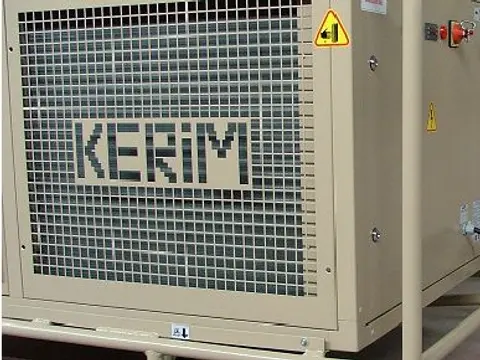
Tent Air Conditioner
Controlled climate for your tents, shelters and temporary structures.
View product -
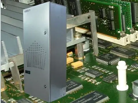
Panel Air Conditioner
Cool, clean, dry control panels, even in your hottest, dirtiest plant areas.
View product -
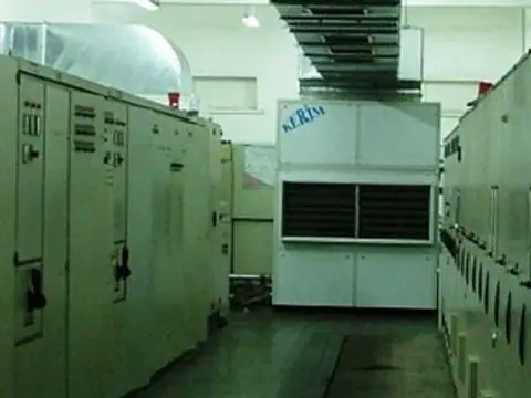
Air / Water Cooled Air Conditioner
Stable room temperatures for your electrical rooms in extreme plant heat.
View product
-
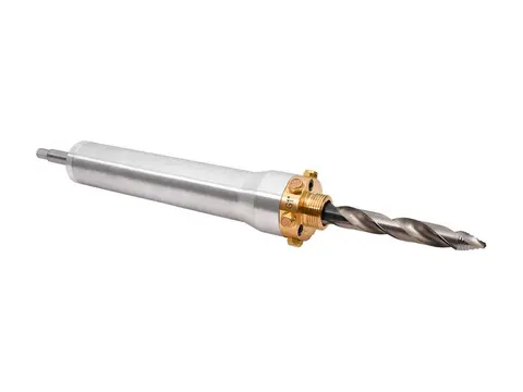
Hot Tapping
Add measurement ports to your live air lines without stopping production.
View product -
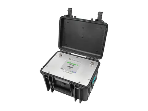
Compressed Air Quality Measurement
Prove your air's ISO 8573-1 purity: particles, oil and dew point.
View product -
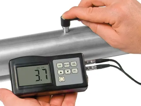
Digital Thickness Meter
Measure the metal left in your receivers and pipework, from the outside.
View product -
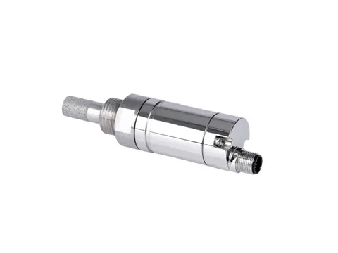
Dew Point Meter
Proof your air is dry, measured at line pressure.
View product -
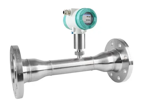
Flow Meter
True standard flow of your compressed air, whatever the line pressure.
View product -

Leak Detector
Hear, locate and cost every compressed air leak in your plant.
View product -
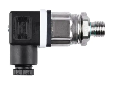
Pressure Sensor
Live pressure data from your compressor room to every point of use.
View product -
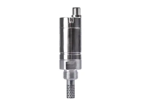
Humidity Meter
Humidity, temperature and dew point from one probe.
View product -
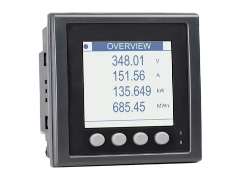
Power Meter
Measure the true power, energy and efficiency of your compressors.
View product
-
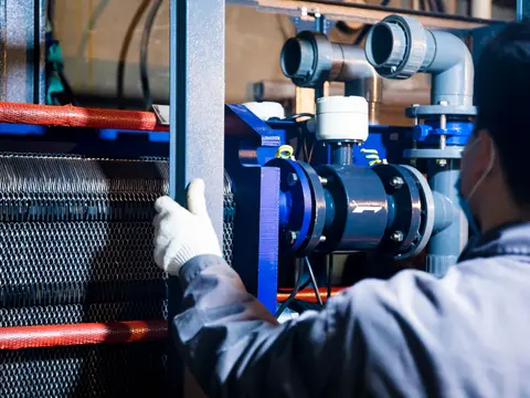
Health Testing of Compressed Air & Gas Dryers
Measured proof your dryer delivers its rated dew point.
View service -
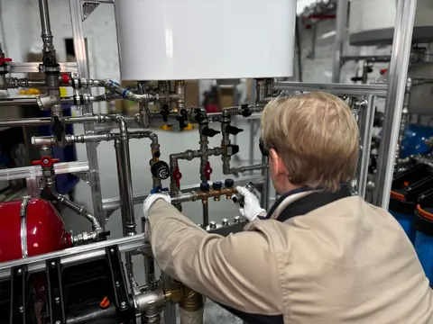
Commissioning and Service of Compressed Air & Gas Dryers
Verified dew point from first start-up through your dryer's service life.
View service -
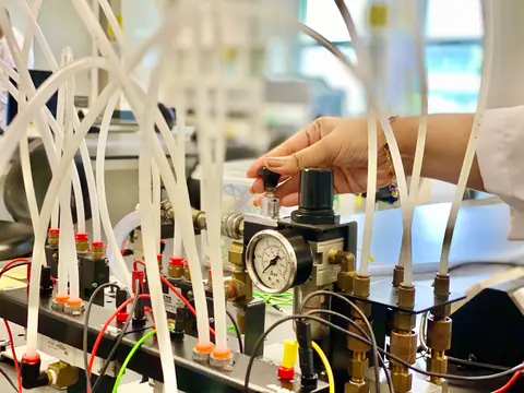
Compressed Air Quality Testing
Measured, documented proof of your compressed air purity class.
View service -
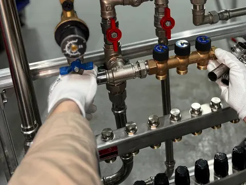
Dew Point Measurement Testing
Verified pressure dew point at the points that matter in your network.
View service -
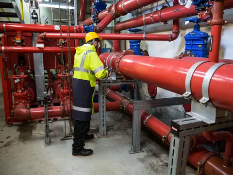
Compressed Air Flow Testing
Measured air demand, leakage and cost for your plant, not estimates.
View service -
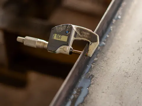
Wall Thickness Testing
Know the remaining wall, corrosion rate and safe life of your equipment.
View service -
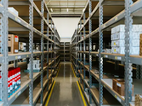
Sourcing
Spares, consumables and whole systems for your plant, sourced globally.
View service
